Angle of Attack


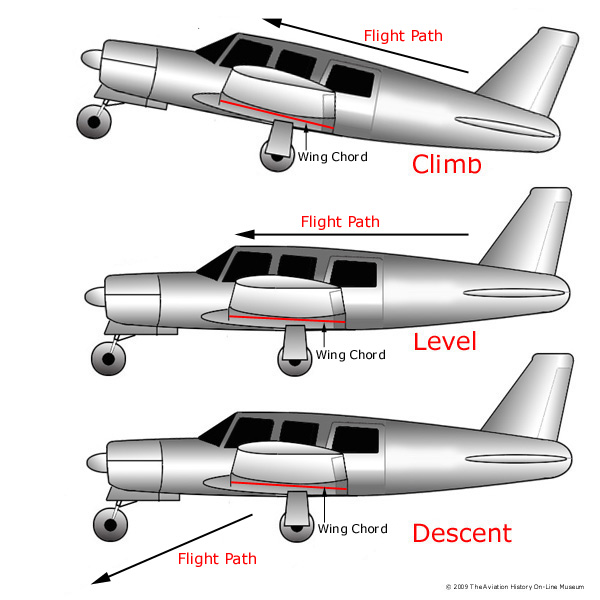
Angle of Attack is used to define the angle between the wing chord  line and the flight path—not the ground. During landing, an aircraft may have a level attitude, but a high angle of attack, because the flight path is downward and the approaching wind is parallel to the flight path. During climb, the airplane can be in a nose-high attitude, but at a low angle of attack.

Angle of Attack is used to define the angle between the wing chord  line and the flight path. This is not to be confused with the relation of the aircraft to the Earth’s surface. This is called the attitude and is seldom, if ever, the same as the angle of attack.

    When the angle is small, the aircraft is said to be at a low angle of attack. When the angle is large, the aircraft is said to be at a high angle of attack.

    Two variables can change the amount of lift generated by a wing in a given configuration.
• The speed of air flowing over the airfoil.
• The angle of attack.
    An increase in speed or the angle of attack will increase both lift and drag. In level flight, lift must equal the weight of the aircraft. If an aircraft weighs 2,000 lbs., the wing must generate 2,000 lbs. of lift. The speed and angle of attack are interchangeable to a point—therefore, for every airspeed, there is a corresponding angle of attack that will produce the same amount of lift.

In order for a wing to produce lift, the air flowing past an aircraft, must be aligned to the airfoil in order to provide a smooth airflow. As a wing increases its angle of attack, airflow can no longer flow smoothly over the wing and eddies or burbles will form, causing the wing to approach its stall speed. When a wing finally stalls, it will no longer produce lift and with weight unopposed by lift, the aircraft will drop towards the ground. With sufficient altitude, stall recovery can be obtained by decreasing the angle of attack.


Angle of Attack is the angle between the wing chord line and the flight path.

An airplane can be stalled at any attitude and at any airspeed such as pulling out of a dive too abruptly or if the airplane is in a steep turn at a high angle of attack, even though the airspeed is high. During dives or turns, centrifugal force will increase load factors and if excessive, this will cause the wing to stall.

    The angle of attack should not be confused with the angle of incidence. The angle of incidence is the angle formed by the wing chord line and the aircraft longitudinal axis. Refer to the page on relative wind for comparison.

Airfoils and Lift

An airfoil is a device which gets a useful reaction from air moving over its surface. When an airfoil is moved through the air, it is capable of producing lift. Wings, horizontal tail surfaces, vertical tails surfaces, and propellers are all examples of airfoils.
Generally the wing of small aircraft will look like the cross-section of the figure above. The forward part of an airfoil is rounded and is called the leading edge. The aft part is narrow and tapered and is called the trailing edge. A reference line often used in discussing airfoils is the chord, an imaginary straight line joining the extremities of the leading and trailing edges.
Bernoulli's Principle: To understand how lift is produced, we must examine a phenomenon discovered many years ago by the scientist Bernoulli and later called Bernoulli's Principle: The pressure of a fluid (liquid or gas) decreases at points where the speed of the fluid increases. In other words, Bernoulli found that within the same fluid, in this case air, high speed flow is associated with low pressure, and low speed flow with high pressure. This principle was first used to explain changes in the pressure of fluid flowing within a pipe whose cross-sectional area varied. In the wide section of the gradually narrowing pipe, the fluid moves at low speed, producing high pressure. As the pipe narrows it must contain the same amount of fluid.In this narrow section, the fluid moves at high speed, producing low pressure.

An important application of this phenomenon is made in giving lift to the wing of an airplane, an airfoil. The airfoil is designed to increase the velocity of the airflow above its surface, thereby decreasing pressure above the airfoil.Simultaneously, the impact of the air on the lower surface of the airfoil increases the pressure below. This combination of pressure decrease above and increase below produces lift.Probably you have held your flattened hand out of the window of a moving automobile. As you inclined your hand to the wind, the force of air pushed against it forcing your hand to rise. The airfoil (in this case, your hand) was deflecting the wind
which, in turn, created an equal and opposite dynamic pressure on the lower surface of the airfoil, forcing it up and back.The upward component of this force is lift; the backward component is drag.

JNTU-HYD : 2-2 (R07,R05,RR,NR) Results

JNTU-HYD : 2-2 (R07,R05,RR,NR) Results Are Released.
B.Tech. II Year II Semester (R07) Supplementary - December, 2009

B.Tech. II Year II Semester (R05) Supplementary - December, 2009

B.Tech. II Year II Semester (RR) Supplementary - December, 2009

B.Tech. II Year II Semester (NR) Supplementary - December, 2009


NOTE : Last date for Recounting/Revaluation is 20-03-2010
Any discrepancy should be forwarded through the Principal before 20-Mar-2010 and no request will be entertained after due date.

JNTU-HYD : B.Pharm 1Year (R07,NR,OR),2-2(R07,NR,OR),3-2(OR,NR) Results


JNTU-HYD : 
B.Pharm 1Year (R07,NR,OR),
2-2(R07,NR,OR),
3-2(OR,NR) Results 

B.Pharamcy III Year II Semester (NR) - December, 2009

B.Pharamcy III Year II Semester (OR) - December, 2009

B.Pharmacy II Year II Semester (R07) Results - December, 2009

B.Pharamcy II Year II Semester (NR) - December, 2009

B.Pharamcy II Year II Semester (OR) - December, 2009

B.Pharamcy I Year (R07) - December, 2009

B.Pharamcy I Year (NR) - December, 2009

B.Pharamcy I Year (OR) - December, 2009

NOTE : Last date for Recounting/Revaluation : 22-03-2010

NASTRAN


NASTRAN, the NASA Structural Analysis System, is a powerful general purpose finite element analysis (FEA) program for use in computer-aided engineering. NASTRAN is a standard in the structural analysis field, providing the engineer with a wide range of modeling and analysis capabilities. Development of NASTRAN was initiated in the mid-1960's by the National Aeronautics and Space Administration to provide an FEA capability for its aerospace research projects. Over the years, NASA has actively maintained and improved NASTRAN such that it remains a state-of-the-art structural analysis system.

NASTRAN applications include almost every kind of structure and construction. Structural and modeling elements are provided for the specific representation of the more common types of structural building blocks including rods, beams, shear panels, plates, and shells of revolution. More general types of building blocks can be treated by combining these simple elements or by using the "general" element capability. The substructuring capability allows (Read More)......

S 2 - Caspar S.1/Heinkel HE 1 ”Hansa” (1921-1931)

An old Swedish proverb says  ”a dear child has many names”. This could really be applied to the ”Hansa”, the low-winged float-plane used in Sweden for almost 30 years. The names and designations were many; Caspar S.I, Hansa Brandenburg,Caspar S.II, Heinkel S.1, HE 1, HE 2, HE 4, S 2, S3, S 4, S 5, S 5A etc…Of course the design and performance was improved during the years, but the main outlines were the same, once drawn by the famous German aircraft designer Ernst Heinkel. The first ”Hansa” (”Caspar S.I”) was made by  Caspar-Werke in Travemünde. Caspar S I was a development of the Hansa Brandenburg W 29, a successful seaplane for reconnaissance and combat duties during WWI. A contract was drawn up for the delivery of a (Read More).....

S 1 - FMV S 21/CFM S 25 (1926-1932)


In 1921, the Army Aviation Company’s Workshops (FMV) at Malmen/Malmslätt near Linköping got an  preliminary order of ten reconnaissance aircraft of Henry Kjellson’s design. The aircraft got the designation S 21 (S = ”Spaning” = ”Reconnaissance” - 21 = 1921, the year of the design). The aircraft had a crew of two - pilot and observer. In these days, aircraft engines was an article in short supply in Sweden. When 22 airship (!) engines type Maybach IVA (260 hp) eventually were obtained from Germany, Kjellson, the chief engineer of FMV, had to design an airframe which suited this engine.

The first S 21 was delivered in 1922. During the trials, several shortcomings were discovered. After some amendments, the other nine airframes were built in 1923-1924. Notwithstanding a long tail, the aircraft was nose-heavy. In the end of 1924, three of the ten aircraft were written(Read More)......

IIT-MADRAS Summer Fellowship Programme 2010

The IITM  Summer Fellowship Programme of two months with stipend is designed to enhance awareness and interest in high quality academic research among young Engineering, Management, Sciences and Humanities students through a goal oriented summer mini project
undertaken at the Indian Institute of Technology Madras.


Eligibility: 

Candidates pursuing third year of B.E./B.Tech./B.Sc.(Engg)/Integrated
M.E./M.Tech. programme, first year of M.Sc./M.A, MBA with 


(Read more....)

JNTU-HYD B.Tech 2-1 Results


JNTU-HYD : B.Tech 2-1(R07,R05,RR,NR) Results Are Out


Check ur results from below links

II Year B.Tech. I Semester (R07) Results - November, 2009

II Year B.Tech. I Semester (R05) Results - November, 2009

II Year B.Tech. I Semester (RR) Results - November, 2009 

II Year B.Tech. I Semester (NR) Results - November, 2009

NOTE : Last date for Recounting/Revaluation: 03-03-2010

Any discrepancy should be forwarded through the Principal before 3rd-Mar-2010 and
no request will be entertained after due date.
B.Tech 2-1 Supplementary Exams will be conducted from 7th JUNE-2010 To 26th JUNE-2010


Introduction to Helicopters

Helicopters come in many sizes and shapes, but most share the same major components. These components include a cabin where the payload and crew are carried; an airframe, which houses the various components, or where components are attached; a powerplant or engine; and a transmission, which, among other things, takes the power from the engine and transmits it to the main rotor, which provides the aerodynamic forces that make the helicopter fly. Then, to keep the helicopter from turning due to torque, there must be some type of antitorque system. Finally there is the landing gear, which could be skids, wheels, skis, or floats. This chapter is an introduction to these components.

 THE MAIN ROTOR SYSTEM
The rotor system found on helicopters can consist of a single main rotor or dual rotors. With most dual rotors,
the rotors turn in opposite directions so the torque from one rotor is opposed by the torque of the other. This
cancels the(Read More).....

Boeing 787 Dreamliner

 Specifications of,

Boeing 787 Dreamliner Long-Range, Mid-Size Airliner, USA.


Key Data:
Crew                                  2
Passenger Capacity          290 to 330 (787-3),
                                           210 to 250 (787-8),
                                           250 to 290 (787-9)
Maiden Flight                   15 December 2009

Dimensions:
Length                      56m, 57m (787-3 and 787-8),
                                  63m (787-9)
Wingspan                  52m (787-3), 60m (787-8), 
                                  63m (787-9)
Fuselage Cross-Section        5.74m
Height                          17.4m, 17m
                                    (787-3 and 787-8 and 787-9)

Cabin:
Configuration               Twin-aisle

Performance:
Maximum Take-Off Weight     165,000kg (787-3),
                                                    219,540kg (787-8),
                                                    244,940kg (787-9)
Range                             14,800km to 15,750km (787-9),
                                        4,650km to 5,650km (787-3),
                                        14,200km to 15,200km (787-8)
Speed                              Mach 0.85

Cargo:
Total Cargo Volume        4,400ft³ (787-3 and 787-8),
                                          5,400ft³ (787-9)

Featured Suppliers:

Aviation Technical Center of Almaty International Airport - Aircraft Maintenance and Aircraft Component and Structural Repair Services
Data Device Corporation - MIL-STD-1553 and ARINC 429 Aerospace Products


AgustaWestland AW101


AgustaWestland AW101 Medium-Lift Helicopter, Italy / United Kingdom


Specification of AW101 are as follows ,

Dimensions:
Length, Rotors Turning       22.8m (74.8ft)
Height Overall                      6.63m (21.75ft)
Length Fuselage                  19.63m (64.4ft)
Width, Overall                     5.67m (18.6ft)
Main Rotor Diameter        18.6m (61ft)
Tail Rotor Diameter           4m (13.11ft)
Number of Blades               5/4
(Main / Tail)

Weights:
Maximum Gross Weight           14,600kg (32,188lb)
(Internal / External Load)
Basic Empty Weight                  8,600kg (18,960lb)
Maximum Useful Load              6,000kg (13,228lb)
Sling Load                                  4,536kg (10,000lb)

Engines:
Type                                  3 x GE CT7-T6A
Take-Off, Rating              3 x 1491kW (3 x 2,000shp)
Maximum Continuous,     3 x 1283kW (3 x 1,720shp)
Rating

Performance:
Maximum Speed                280km/h (150kt)
Rate of Climb                     10.16m/s (2,000ft/min)
Hovering IGE                      2,316m (7,600ft)
Hovering OGE                    1,067m (3,500ft)
Service Ceiling                    4,575m (15,000ft)
Maximum Range                Over 1,389km (750nm)
(Internal Fuel Tank)
Maximum Endurance          6 hours
(Internal Fuel Tank)

Featured Suppliers:
Data Device Corporation - MIL-STD-1553 and ARINC 429 Aerospace Products
Evonik Foams - SOLIMIDE Polyimide Acoustical and Thermal Aircraft Insulation Foam
TITAL - Titanium Investment Castings, Aluminium Investment Castings, HERO Premium Casting and Rapid Prototyping
Wheelabrator Group - Peening and Surface Engineering Solutions.


Happy Valentine's day

Belle Aerospace Textron X-22a

First Flight: March 17, 1966
Mission:
Test viability of ducted lift propellers for VTOL aircraft
Major Accomplishments:  Provided long term test bed for VTOL research

Power Source: 
4 GE YT58-GE-8D shaft turbine engines
Wing Span: (Front:) 22' 11"
Wing Span: (Rear:) 39" 3"
Length: 39' 6"
Weight (Loaded): 18,016 lbs
Maximum Achieved Speed: 255 mph
Additional Information: 2 X-22a were constructed. The first suffered heavy damage in August of 1965 and remaining parts were used to complete the second X-22a. Flights were conducted from March, 1966 to October, 1984.

Hotelicopter


For more pics visit www.aerospice9.co.cc

JNTUH Aero 4-1 Supply 2009 papers


Aeronautical 4-1 R05 supply 2009 papers..


JNTUH first year previous question papers


JNTU Hyderabad First year Engineering all Branches regular and supplies Previous Question Papers........click on required paper to download.


01) NR10101 English
02) NR10102 MATHEMATICS I-set1 
03) NR10103 ENGINEERING-PHYSICS
04) NR10104 Engineering-Chemistry
05) NR10105 ENGINEERING-MECHANICS-set1 
06) NR10106 INTRODUCTION-TO-COMPUTERS-set1 
07) NR10107 ENGINEERING-GRAPHICS-set1 
08) NR10108 INORGANICANALYTICALCHEMISTRY 


09) NR10201 AppliedPhysics 
10) NR10202 COMPUTERSANDINTORMATIONTECHNOLOGY 
11) NR10203 C-AND-DATA-STRUCTURES 
12) NR10204 NETWORK THEORY 
13) NR10205 SEME CONDUCTORS DEVICES AND CIRCUITS 

14) NR10802 STRENGTH-OF-MATERIALS-set1 
15) NR10803 INTRODUCTION-TO-CHEMICAL-ENGINEERING 

16) NR11801 METALLURGICAL-ANALYSIS-set1

17) R07A1BS01 ENGLISH 
18) R07A1BS02 MATHEMATICS-I 
19) R07A1BS03 EngineeringPhysics 
20) R07A1BS04 APPLIED-CHEMISTRY 
21) R07A1BS05 APPLIED-PHYSICS 
22) R07A1BS06 MATHEMATICAL-METHODS 
23) R07A1BS07 ENGINEERING-CHEMISTRY 
24) R07A1BS08 PHYSICAL-CHEMISTRY 
25) R07A1BS09 NUMERICAL-METHODS 


AIRBUS AN ECO-EFFICIENT ENTERPRISE


Airbus is set to contribute to sustainable growth - a growth compatible with the environment, and to
continue delivering solutions to a world that wants greater mobility… and a cleaner and quieter
future.
Airbus is totally committed to ensuring that air travel continues to be one of the safest, and most
eco-efficient means of transportation. Environmental, health and safety (EHS) considerations have
long been an integral part of its activities at all levels of the company, and are a key priority in the
development of all new techniques, products and processes. Today, it makes even stronger
business sense.
Despite the fact that the aviation’s contribution to overall CO2 man-made emissions is expected to
remain low compared to other sectors within the coming decade (ca. two per cent of man-made
CO2 emissions), no other sector makes such important relative investments and efforts to decouple
its growth from the associated environmental impacts.
As an aircraft manufacturer, Airbus is committed to ensuring that growth of our industry is Eco-
Efficient.
Eco-Efficiency is not about greenery.
Eco-Efficiency is a management practice, allowing being more environmentally responsible while
bringing more profitability and social benefits.
In brief, it is about creating more value with less environmental impact, enlarging the scope to the
full lifecycle and anticipating issues at the earliest possible stage. Eco-Efficiency aims at
maximizing the benefits delivered by our products and services to our customers and other
stakeholders while minimizing the Environmental impact throughout their lifecycle.
Becoming more Eco-Efficient makes good business sense. Building aircraft Eco-Efficiently on the
ground that will operate Eco-Efficiently in the air is the Company’s core business.
In January 2007, Airbus became the first company in the aerospace manufacturing sector to
receive the ISO 14001 environmental certification covering all its 15 European manufacturing
sites and all its product related activities throughout a full lifecycle approach.
This means that Airbus systematically uses a robust Environmental Management System
(EMS) to continually monitor and minimize the environmental impacts of Airbus processes and
products at each stage of the activity throughout the lifecycle.
Design
In the frame of its innovative EMS, based on recognised standards, Airbus has performed a
streamlined lifecycle analysis and set-up a methodology for mapping aircraft environmental
impacts throughout the entire product lifecycle. Performed on a long-range programme in a pilot
phase, this approach has enabled Airbus to identify the environmental issues that matter and to
address them appropriately.

Minimising environmental impacts at source is paramount as design exerts a major influence on
each dimension of aircraft’s environmental performance. Environment is therefore part of toplevel
requirements for the design of any new product. That’s why 80 per cent of the company’s
€2 billion Research & Development (R&D) has environmental benefits for current and future
aircraft. Airbus’ Research & Technology (R&T) efforts are focused on investigating, testing,
validating and optimising the most advanced technologies, design features, configurations and
architectures that will lead to aircraft generating fewer emissions and less noise, while carrying
a maximum payload over the mission range.
Reducing engine emissions is a priority for Airbus. In addition to optimised propulsion systems
and overall aerodynamic efficiency, a major area of research is the continuous and progressive
introduction of advanced materials and new processes to reduce the basic weight of an aircraft
to minimise fuel consumption and corresponding engine emissions. The A380 is the first
commercial aircraft to incorporate as much as 25% composites. With a carbon-fibre-reinforced
plastic composite centre wing box, a weight saving of up to 1.5 tonnes has been achieved. With
less than three litres per passenger per 100 kilometres the A380 has a very low fuel burn. This
corresponds to less than 75 grammes of CO2 emissions per passenger per km.
Reducing noise at source is a similar priority. The company is not only working on low-noise
nacelle designs, acoustic treatments, and low engine noise technologies hand-in-hand with
engine manufacturers. One such innovative project is the 0-splice inlet technology for engine
nacelles to reduce fan noise. It also contributes to the remarkable noise performance of the
A380 that shows unprecedented certified noise levels with a 17-EPNdB cumulative margin to
the most stringent ICAO Chapter 4 standard, and satisfies the noise requirements of the most
restrictive international airports.
Airbus has also taken on board an ambitious Research and Technology Vision and signed on
13th October 2006 the Memorandum of Understanding to establish the Aeronautics Joint
Technology Initiative (JTI) “Clean Sky”. This JTI is a large seven-year industry-driven
technological research programme that will radically improve the impact of air transport on the
environment through technologies and solutions enabling step changes in the reduction of fuel
consumption, emissions and noise for future aircraft.
Supply chain
Aircraft are one of the most complex products, integrating hundreds of thousands of
components. Therefore, collaborating with the entire supply chain is key to ensuring reliability at
each subcomponent level, and delivering products on time and within budget that satisfy the
highest environmental and quality standards. Environmental requirements are included in the
selection of Airbus Suppliers and are introduced in contractual agreements. Airbus Suppliers
are expected to provide reliable environmental data on the products delivered and to develop
and implement an Environmental Management System.
Tracking and managing hazardous materials has also been for long time crucial to Airbus.
A proactive approach developed in close collaboration with main EU and US aerospace
companies should enable Airbus to best manage its compliance with environmental laws and

AIR POLLUTION by AIRPLANES

 AIR POLLUTION


Aviation are the power of present Era. But we don't know that they are one of the main cause of Air pollution. The air we breath contain pollution in which air crafts and airplanes are contributing almost 35% by a scientific research. We enjoy travelling planes and pay a big for them, but we dont know we are buying disease such as cancer, skin infection, skin cancer and such dangerous diseases. Scientist must play a part in reducing this cause. They must increase engine efficiency and make such type of fuel that cause less pollution. Right Now! airplanes are the main source of Communication, transport, and big consumer of OIL. Oil is a lessing day by day and airplane can consume even 1 ton (1000 liters) per flight and you may estimate how expensive and how destructive to our environment,. Engineers and scientist must find out new fuel type like green fuel which reduces these factors and make the aviation save for environment and able us to breath in REALLY clean environment.

Aeronautics 4-1 Reguler 2008 JNTU


JNTU Aeronautical Engineering 4th year 1st sem all regular question papers........


AeroSpice Live

AeroSpice Adds

AeroSpice pic

AeroSpice pic
Try your goals untill ur dreams comes to true

AeroSpice ads

Followers